SSRS

SSRS Line Chart with Data Tables (Excel Style)

SSRS Line Chart with Data Tables (Excel Style)

It takes a lot of discipline and dedication to run a blog properly and that is one of the main reasons why I admire bloggers and tech gurus like Chris Webb (who has been putting out high quality blogs for ages in a consistent manner!). Sadly, I am not very disciplined when it comes to writing blogs and it takes a significant external force to make me write nowadays. I had written a blog almost 3 years ago on how to create SSRS charts with data tables like in Excel and from then onwards, I have had a lot of readers ask me on how to do the same with line charts (both through comments as well as emails). I knew it was possible but was too lazy to write a blog on it, until I had 2 readers ask me the same question yesterday in the comments. Finally, I decided to check it out and write about it. The solution is not perfect and is more of a workaround but should be ok for most of you I guess.

The allure of Rolex watches is undeniable. Renowned for their precision, luxury, and timeless style, Rolex has become a symbol of status and success. However, owning a genuine Rolex watch comes with a hefty price tag, making it unattainable for many watch enthusiasts. This is where Rolex replica watches come into play. In recent years, high-quality Rolex replicas have gained immense popularity for their exceptional craftsmanship and resemblance to the real deal. In this article, we’ll explore the world of Rolex replica watches, where to find the best super clone 1:1 copies, and what you should consider before making a purchase.

The Rise of Rolex Replica Watches

The demand for Rolex replica watches has grown steadily over the years. These replicas have become more than just imitations; they are often referred to as “super clones” due to their astonishing accuracy in replicating the original Rolex design, movement, and functionality. The rise of super clone Rolex watches can be attributed to several factors:

Affordability: Authentic Rolex watches come with a price tag that often exceeds the budget of the average consumer. Rolex replicas, on the other hand, offer a cost-effective alternative for those who desire the prestige of a Rolex without breaking the bank.

Quality Improvements: Advances in manufacturing techniques and materials have enabled replica watchmakers to produce highly detailed and meticulously crafted super clones that are almost indistinguishable from the genuine Rolex timepieces.

Accessibility: With the advent of e-commerce, it has become easier than ever to find Rolex replica watches online. Numerous websites and sellers cater to this growing market.

Where to Find the Best Super Clone Rolex 1:1 Copies

While there are numerous sources for Rolex replica watches, it’s essential to exercise caution when making a purchase. Counterfeit products and low-quality imitations are abundant in the market, so it’s crucial to do your research and buy from reputable sources. Here are some tips to help you find the best super clone Rolex 1:1 copies:

Reputable Online Sellers: Several trusted online stores specialize in high-quality replica watches. Look for websites with a good reputation, customer reviews, and clear policies regarding the quality and authenticity of their products.

Ask for Recommendations: Seek advice from fellow watch enthusiasts who have experience with replica Rolex watches. They may recommend trustworthy sellers or websites.

Study the Details: Pay close attention to the product descriptions, specifications, and high-resolution images provided by the seller. The best super clone Rolex watches will closely resemble the authentic models, down to the finest details.

Reviews and Feedback: Read reviews and feedback from previous customers to gauge the quality and reliability of the seller. Genuine customer testimonials can provide valuable insights.

Warranty and Return Policy: Ensure that the seller offers a warranty or return policy, as this indicates their confidence in the product’s quality.

Considerations Before Purchasing a Rolex Replica

Before purchasing a Rolex replica watch, it’s essential to consider the following:

Legal and Ethical Considerations: Rolex is a protected trademark, and selling counterfeit Rolex watches is illegal in many jurisdictions. Ensure that you understand the laws in your area and the potential consequences of owning a replica watch.

Your Motivation: Be clear about your reasons for buying a replica. If you’re looking for a quality timepiece that emulates Rolex style, a super clone 1:1 copy may be a suitable choice. However, if your intention is to deceive or pass it off as an authentic Rolex, this is both unethical and potentially illegal.

Maintenance and Care: Just like genuine Rolex watches, replicas require maintenance to ensure their longevity and accuracy. Be prepared to invest in regular servicing.

Conclusion

Rolex replica watches, especially super clone 1:1 copies, have become a popular choice for watch enthusiasts who appreciate the elegance and craftsmanship of Rolex timepieces but may not have the financial means to own an authentic Rolex. While replica watches offer an affordable alternative, it’s crucial to exercise caution, do thorough research, and buy from reputable sources to ensure you receive a high-quality product that meets your expectations. Keep in mind the legal and ethical considerations surrounding replica watches and enjoy your Rolex-inspired timepiece responsibly.

For illustrating the solution, I am using a simple dataset which shows the sales by Product and Month.

To follow this solution, you must be familiar with the technique I mentioned in the previous article. If you have not read that, please the previous article first and then follow the steps below 1) A lot of readers already found out that if the technique described in the previous article was used, then we will only get points and not actual lines. So, the very first step here is to modify the source query such that for every actual point in the line chart, we get 2 more points which gives the start and end for that point. With this, now we will have a line joining 3 points for what would just have been one point before.

;WITH Src
AS (SELECT Product,
MonthNo,
Month,
Sales,
CASE
WHEN MonthNo = 12 THEN NULL ELSE (lead(Sales, 1, NULL) OVER (PARTITION BY Product ORDER BY MonthNo) + Sales) / 2
END AS LeadSales,
CASE
WHEN MonthNo = 1 THEN NULL ELSE (lag(Sales, 1, NULL) OVER (PARTITION BY Product ORDER BY MonthNo) + Sales) / 2
END AS LagSales
FROM (<Source Query>) AS O)
SELECT Product,
MonthNo,
Month,
‘1’ AS Type,
CAST (LagSales AS FLOAT) AS Sales
FROM Src
UNION ALL
SELECT Product,
MonthNo,
Month,
‘2’ AS Type,
CAST (Sales AS FLOAT) AS Sales
FROM Src
UNION ALL
SELECT Product,
MonthNo,
Month,
‘3’ AS Type,
CAST (LeadSales AS FLOAT) AS Sales
FROM Src;

Note that LeadSales column is actually the (Sales for next point + Sales for Current Point) / 2 and LagSales column is actually the (Sales for previous point + Sales for Current Point) / 2. This will help us get a smooth line when we join our different lines. Also, we have to ensure that for the first and last points, NULL values are assigned. The bottom part of the query brings all three columns (Sales, LeadSales, LagSales) into a single column called Sales but each one is assigned a different Type.

2) Repeat the steps 2 and 3 in previous article to make the matrix and the two rows above it.

Also add the Type column to the row group, delete the columns only and then filter the Type group for 2 only. The reason is that we only want the actual Sales to be shown in the data table, which is 2. Type 1 and 3 are used for the sole purpose of making the line chart.

3) Now you should be able to follow the rest of the steps in the previous article with the sole exception that you will be using a line chart and not a bar chart.

Make sure that you set the CustomInnerPlotPosition and CustomPosition appropriately like in step 10 in the previous article, so that graph appears continuous. I used the below settings for this line chart.

4) Instead of step 11 in the previous article, I chose to make a new column to the left for the vertical axis, and just made sure that the vertical axis for the line charts all have the same scale.

Note that the series expression for this column is just 0, and there are no category or series group. This ensures that we just get a dummy line for the axis. You can start hiding the orders to ensure that the graph looks continuous.

5) I also added an expression such that the markers and tooltips only show if the type is 2.

6) With all these changes and a bit of formatting, we can get the below result

This should be good for most people. However, there is one minor drawback which is that the lines do not join that smoothly. I have just zoomed in one part so that you can see the issue. Maybe, this could be solved by fiddling along with the properties some more, but I feel this is not that big of an issue.

Hopefully this will put to rest some of the questions I keep getting on data tables in SSRS, so that I can go back to my lazy self (just kidding)

Posted by SQLJason, 18 comments

How to make Map Reports in SSRS

I was going through some of my old documents and found this article on map reports which I had written for a SSRS book (which didn’t go through because of some time related issues). I thought it might be useful to those who are looking to explore map reports in SSRS. So here it goes:- Map reports have been a part of SQL Server Reporting Services from SSRS 2008 R2. However, they are usually a grey box for developers and hence, not been used to their full potential in most of the organizations. This chapter will introduce you to the basic concepts involved in map reports and then take you through some of the common scenarios involved while building map reports.

Basic Concepts

1) Geometry and Geography: These are the two spatial data types that are available in SQL Server 2008 and above. Geometry imagines that the world is a flat rectangle while Geography takes the curvature of the spherical earth into account. Depending on your application, you can choose between the two data types for your spatial purposes. Geography data types would be more precise over long distances as the earth is actually spherical, but it would require more overhead in setting up the spatial data as additional parameters have to be provided to account for the roundness of the earth. Geometry on the other hand is easier to setup but might not give you the precision over long distances.

2) Source for Map Reports: SSRS 2008 R2 and above allows two main map sources – ESRI Shapefiles and SQL spatial. Shapefiles are a popular geospatial vector data format which can be used in a lot of geographic information softwares. A shapefile will consist of at least 3 mandatory files (of extension .shp, .shx and .dbf) to store core data and might have some other files for improving performance. Apart from shapefiles, the spatial data can be stored in SQL Server database using the data types geography or geometry and used as a source for SSRS map reports. SSRS also has a predefined set of maps in the Map Gallery, which is essentially spatial data embedded in reports and this can also be used as a source for your map reports.

3) Layer Types in Map Reports: There can be 4 types of layers in SSRS Map reports namely Polygon, Line, Point and Bing Map. Polygon layers are used for displaying outlines of areas like administrative boundaries for countries, states, etc. Line layers are used for displaying the lines for routes, roads, paths, etc. Point layers are usually used for displaying the markers for point locations. The Bing Map layer adds a background of Bing Map tiles that correspond to the spatial data available in the map viewport.

Prerequisites To recreate the scenarios explained in this chapter, you would require the following:-

1. SQL Server 2012. You can download an evaluation copy from http://tinyurl.com/SQL2012Eval

2. AdventureWorksDW2012 Database. You can download it from http://tinyurl.com/Adw2012SqlDB

3. AdventureWorks Multidimensional Models for SQL Server 2012. You can download it from http://tinyurl.com/Adw2012CubeDB

4. Some sample shapefiles for the United Kingdom, which can be downloaded from http://tinyurl.com/ShapefileUK

Initial Setup

1. Start by creating a new report project using SQL Server Data Tools (SSDT).

2. Design a new shared data source based on the Microsoft SQL Server provider that connects to the sample AdventureWorksDW2012 database and name it DS_SQL.

3. Design a new shared data source based on the Microsoft SQL Server Analysis Services provider that connects to the sample AdventureWorks Multidimensional database and name it DS_SSAS.

I) Creating Map Reports from Shapefiles

This section will demonstrate how to create a map report from a shapefile and visualize it with the measures present in your relational or multidimensional database.

1. Add a new report to the project and name it ‘1 Report from Shapefiles

2. Create a new data source which points to the shared data source, DS_SQL

3. Design a dataset called DST_Analytical_UK_C and populate it with the SQL query below

SELECT ‘England’ AS Country, 500 AS Sales

UNION ALL

SELECT ‘N Ireland’ AS Country, 300 AS Sales

UNION ALL

SELECT ‘Scotland’ AS Country, 350 AS Sales

UNION ALL

SELECT ‘Wales’ AS Country, 200 AS Sales

4. Drag and drop a map report item from the toolbox to open the Map Wizard. In the first screen, select ESRI Shapefile as the source of spatial data. Browse to the folder which has the saved maps for the sample UK shapefiles and select GBR_adm1.shp. Click on Next.

5. You should be able to view the map and change its resolution or crop it in this screen. You can also add a Bing Maps layer in this screen if needed. Click on Next.

6. Choose the Map Visualization in this screen. Since we have chosen a polygon shapefile, we get the options for Basic Map (which just displays the map), Color Analytical Map (which visualizes the data by varying color) and Bubble Map (which visualizes the data by bubbles of varying sizes). The last two options would require a dataset for getting the measure information to visualize data. Choose the Color Analytical option for now and click on Next.

7. In the next screen, select the analytical dataset DST_Analytical_UK_C that we had created in Step 3.

8. In this screen, we will have to specify the match fields in the spatial and analytical data. Select the checkbox for NAME_1 in the spatial dataset field and select Country in the dropdown for analytical dataset field. You can see the selected fields getting highlighted in the window panes below. Click on Next.

9. Choose an appropriate theme and select [sum(sales)] from the dropdown list of the Field to visualize option. Choose the Color Rule as Red-Yellow-Green. You can choose to display the labels also if you want. Click on Finish. 10. Now you can preview the report and see your first map report.

FAQs regarding Map Reports from Shapefiles

1) Why is that some of my map regions are not getting visualized and are being displayed in white color?

This is a clear indicator that the names in the match fields for the spatial and analytical data are not the same. An example is present in our current example where DST_Analytical_UK_C has a field value of ‘N Ireland’ while the shapefile has a field value of ‘Northern Ireland’. You can change the value to Northern Ireland in the analytical query but this might not be a valid scenario in most of the cases where the data comes from the Data Warehouse and we would not want to tamper with the Data Warehouse. In such cases, we can change the field value of the shapefile by going to the design mode for the report, right clicking on the polygon region (in this example, Northern Ireland) in the map report item and selecting Embedded Polygon Properties. Now the NAME_1 field can be changed from ‘Northern Ireland’ to ‘N Ireland’ in the popup window and all the regions should be visualized now.

2) Why is it that I am getting a system exception when I try to deploy some of my map reports?

This happens normally when you are working with shapefiles in excess of 4MB. By default, the maximum size of a rdl report which can be deployed is 4MB. This can be easily changed by replacing <httpRuntime executionTimeout = “9000” /> with <httpRuntime executionTimeout = “9000” maxRequestLength=”1000000″ /> in the Web.config file which by default is found in C:Program FilesMicrosoft SQL ServerMSRS11.SQL2012Reporting ServicesReportServer. The reporting services might need to be restarted for the change to be reflected.

3) OK, I have succeeded in deploying my report to the ReportServer. However the report takes a long time to render. Why is that?

This should come as no wonder if you are working with large shapefiles. Most of the shapefiles that are available online exceed 8MBs and it would be prudent to trim them down the size by changing the resolution in the map wizard. For example, I was able to trim down the size for the current report using this method from 8.5MB to less than a MB without much difference to the map outlines. Another alternative would be to upload the Shapefiles to the ReportServer and then use them as the source for your map reports as is shown in this link http://tinyurl.com/Jason-UploadSHP. This could help in decreasing the rendering time as well as making the shapefiles available for other reports.

4) Why is it that I see only the maps for USA in the Map Gallery? How can I add my own maps there?

Currently, only the maps for USA are there in the Map Gallery. However, you can add your own maps by following the instructions in this link http://tinyurl.com/Jason-AddMapToGallery

5) Where do I find some sample shapefiles to start exploring map reports? There are plenty of sites which offer free shapefiles for at least the country level administrative boundaries. One of them is http://diva-gis.org. For more detailed level shapefiles (like zip codes for Netherlands), you might need to buy it from some vendors or make your own shapefile using tools like ArcGIS.

II) Creating Map Reports from SQL Spatial Data

This section will demonstrate how to create a map report from spatial data stored in SQL Server and visualize it with the measures present in your database.

1. Create a new table called dbo.GBR_adm2 in the database which corresponds to the shapefile GBR_adm2 in the sample. (Read the FAQs below on how to import spatial data to the database).

2. Add a new report to the project and name it ‘2 Report from SQL Spatial

3. Create a new data source which points to the shared data source, DS_SQL

4. Design a dataset called DST_Spatial_UK_D and populate it with the SQL query below

SELECT NAME_1, NAME_2, geom

FROM dbo.GBR_adm2

Note that the table dbo.GBR_adm2 contains the equivalent spatial data of the GBR_adm2 shapefile in our samples.

5. Design a dataset called DST_Analytical_UK_D and populate it with the SQL query below

SELECT NAME_1, NAME_2, LEN(NAME_2) AS Sales

FROM dbo.GBR_adm2

6. Drag and drop a map report item from the toolbox to open the Map Wizard. In the first screen, select SQL Server Spatial Query as the source of spatial data. Click on Next.

7. Choose DST_Spatial_UK_D as the spatial dataset in the screen and click on Next.

8. You should be able to view the map and change its resolution or crop it in this screen. You can also add a Bing Maps layer in this screen if needed. Click on Next.

9. For the purpose of exploring a new map visualization, select Bubble Map and click on Next.

10. Choose DST_Analytical_UK_D as the analytical dataset and click on Next.

11. Select NAME_2 as the matching field for both spatial and analytical datasets and click on Next.

12. Select the checkbox for Use bubble sizes to visualize data and choose the Data Field as [Sum(Sales)]. Click on Finish.

13. Now you can preview the report and see the result.

III) Parameterizing Map Reports

Most of the times, it is necessary to add report parameters to filter out the data so that we can focus better on a particular region. This section will provide a walkthrough on how to add parameters to a map report

1. Open the 2 Report from SQL Spatial report and add a new dataset, DST_RP_Country with the query given below.

SELECT DISTINCT NAME_1

FROM GBR_adm2

2. Add a new report parameter, RP_Country with available values from the DST_RP_Country dataset.

3. Modify the query of the DST_Spatial_UK_D dataset as shown below

SELECT NAME_1, NAME_2, geom

FROM GBR_adm2

WHERE (NAME_1 = @RP_Country)

4. Modify the query of the DST_Analytical_UK_D dataset as shown below

SELECT NAME_1, NAME_2, LEN(NAME_2) AS Sales

FROM dbo.GBR_adm2

WHERE (NAME_1 = @RP_Country)

5. It would be good idea to add a Bing Map layer to the background so that we can understand the location better. For this, click on the polygon layer to display the Map Layers panel on the right hand side. Then click on the Add Layer icon and select the Tile Layer option from it.

6. Click on Preview and you can see that the map changes with the selected parameter value.

IV) Implementing Drill Down in Map Reports

This section will provide details on how you can implement the drill down feature in map reports. For the same, we will be making use of the two reports that we have already created – 1 Report from Shapefiles as the parent report and 2 Report from SQL Spatial as the child report.

1. Open the report – 1 Report from Shapefiles in design mode and click on map report item to bring the Map Layers panel on the right hand side.

2. Right click on the polygon layer and select the Polygon Properties.

3. Select the Action tab on the property popup window, and select the Go to Report radio button.

4. Specify the 2 Report from SQL Spatial report as the child report and map the RP_Country parameter with the Country field as shown in the image below. Then click on OK.

5. Once this is done, you can preview the report and see that the second report gets displayed with the appropriate filtered data on clicking a particular country in the first report.

V) Aggregating Spatial Data in Map Reports

Just like we aggregate our normal relational data, there might be scenarios where we would like to aggregate spatial data and display it in a report. An example would be to aggregate custom sales regions of an organization at a country level. This example would take you through such a similar implementation.

1. Create a new table dbo.GBR_adm1 with spatial data which corresponds to the shapefile GBR_adm1 in the samples.

2. Add a new column called Sales_Region to the table dbo.GBR_adm1 and give a value of North to Scotland and Ireland, and South to England and Wales.

3. Create a new report 3 Aggregate Spatial Data and add a dataset called DST_Spatial_AggUK with the query below

SELECT SalesRegion, geography::UnionAggregate(geom) AS geom

FROM GBR_adm1

GROUP BY SalesRegion

Note that geography::UnionAggregate and geometry::UnionAggregate are two new spatial functions introduced in SQL Server 2012 to aggregate geography and geometry data respectively.

4. Now make a Basic Map report with the above dataset and you can see the result below when you preview the report

The same effect can also be done by aggregating the spatial data in the reports instead of in the query.

1. Create a dataset called DST_Spatial_UK with the query below

SELECT SalesRegion, geom

FROM GBR_adm1

2. Create a Basic Map report with this dataset as the source.

3. Click on the map viewport to bring the Map Layers panel on the right. Click on the polygon layer, and then press F4 to bring the property panel.

4. Modify the VectorData property as =Union(Fields!geom.Value)

5. Click on the Group property and add the SalesRegion field as shown in the image below. Click on OK.

6. Preview the report now and you should see the map of UK aggregated by SalesRegion as in the example above.

FAQs regarding Map Reports from SQL Spatial Data

1) All of my map reports are visualized in a single color even when I have not chosen the Basic Map option. Why is that?

SSRS has some color distribution options which govern the way colors are visualized in your map reports. By default, it is kept to Optimal option which create ranges that automatically adjust distribution to create balanced sub ranges. You might want to change it to EqualInterval option (which creates ranges that divide the data into equal range intervals), EqualDistribution option (which creates ranges that divide that data so that each range has an equal number of items) or Custom option (where you can specify your own number of ranges to control the distribution of values). This can be done by right clicking on the map layer and selecting Layer Color Rule option.

2) How do I import my shapefiles to SQL Server?

Currently, SQL Server does not have a built-in option to import shapefile data to SQL Server. One of the most popular ways to import shapefile data to SQL Server is by using the free tool Shape2SQL. This has a single screen, easy to use GUI and can be downloaded from http://tinyurl.com/Shape2Sql.

There are a few bugs with this tool and from my personal experience, in case you are not able to see the imported table in the database, it might be worthwhile to create the table structure beforehand and then run the software again

3) How do I add my own custom locations as a point layer in map reports?

There are many sites like http://tinyurl.com/FindLatnLong which will return the latitude and longitude if you enter your address. This can be converted to spatial data using the function STPointFromText(). An example is shown below

1. Create a sample table

CREATE TABLE [dbo].[MyHangouts](

[ID] [int] IDENTITY(1,1) NOT NULL,

[Location] [varchar](255) NULL,

[Latitude] [float] NULL,

[Longitude] [float] NULL,

[PostCode] [varchar](20) NULL,

[GeoL] [geography] NULL

) ON [PRIMARY]

2. Insert some data with the latitude and longitude

INSERT INTO [dbo].[MyHangouts] ( [Location], [PostCode], [Latitude], [Longitude] )

VALUES (‘Home’,’NC 28210′,35.1537875,-80.8502022),

(‘Office’,’NC 28211′,35.1493742,-80.8272008),

(‘PetSmart’,’NC 28217′,35.1385661,-80.8764557),

(‘The EpiCentre’,’NC 28202-2538′,35.225324,-80.842187),

(‘Library’,’NC 28211′,35.1513557,-80.8225257)

3. Update the spatial data column using the STPointFromText function

UPDATE [MyHangouts]

SET [GeoL] = geography::STPointFromText(‘POINT(‘ + CAST([Longitude] AS VARCHAR(20)) + ‘ ‘ + CAST([Latitude] AS VARCHAR(20)) + ‘)’, 4326)

geography::STPointFromText(‘POINT(‘ + CAST([Longitude] AS VARCHAR(20)) + ‘ ‘ + CAST([Latitude] AS VARCHAR(20)) + ‘)’, 4326)

4) Can I create my own custom shapes in the map reports?

Yes, you can create your own custom shapes in the map reports as long as you are able to provide the location points for it. You can use online image mapping tools like http://tinyurl.com/ImageToMaps to get the point locations and then use the STPolyFromText() to convert it into spatial data. For eg, I have used a spatial query to get the result below

The query is available in http://tinyurl.com/SpatialLogo if you want to have a further look. Conclusion SSRS spatial features take up the charting possibilities to a whole new level. In addition to the normal geo-spatial reporting capabilities, we can also use the spatial features to basically create any shape or chart that we require and visualize it with data. All we need are the locations of the shape as well as a little bit of creativity.

Posted by SQLJason, 9 comments

Designing Bullet Graphs in SSRS – Part 3

The concepts in this 3 part blog series are heavily borrowed from the book Information Dashboard Design, authored by the data visualization guru - Stephen Few and is going to concentrate on the following topics:-

I) How to make Bullet Graphs in SSRS
II) Deciding the Color
III) Multiple points of comparison
IV) Alternatives to bar
V) Differentiating measures that need to be read differently
VI) Positive and negative values
VII) Values within a distribution
VIII) Future Projections In my previous post (Designing Bullet Graphs in SSRS – Part 2), I showed how to make alternatives to bar, how to differentiate measures and how to show positive and negative values in bullet graphs developed in SSRS. This post will touch upon the final 2 topics. VII) Values within a distribution Sometimes the value displayed in a bullet graph needs to be compared to the distribution of an entire set of values. Lets say, a teacher needs to see how individual students performed with respect to the class average. For that, I have made a sample dataset shown below L1, L2, L3 and L4 are limits of the three ranges, Score is the score for that student, Avg is the average for that Subject in the class. Now let’s see how to make bullet charts for the data shown above. 1) Drag and drop a table in the report layout. Put Subject field in the Rows and then put a bullet chart in the data field. Select Score as the LinearPointer1 and Avg as LinearPointer2. 2) Add 3 ranges as shown in step 5 of How to make Bullet Graphs in SSRS - Designing Bullet Graphs in SSRS – Part 1. The upper and lower limits should be L1 & L2, L2 & L3 and L3 & L4 respectively for the three ranges. 3) Change the Scale properties to a minimum of 40 and maximum of 100 (we are hardcoding it now but ideally you should use expressions). Also change the Number format to #,00 instead of percentage. 4) Change the bar to a cross mark as per the technique shown in Alternatives to BarDesigning Bullet Charts in SSRS – Part 2. Now the result should be similar to the image shown below 5) Add 2 more ranges so that the empty spaces (for eg, 40 – 60 for English) can be filled. For that, right click on the scale and then select the Add Range option. 6) Select the Start range as 40 and End range as L1. Set the Placement relative to scale option to Cross. Also, change the Fill color to No color. Repeat the same for the second range but set the Start range as L4 and End range as 100. Now, with a bit of the formatting techniques described in the previous posts, you should get the desired result. VIII) Future Projection With the normal bullet chart, it is easy to compare a measure with another measure, say Sales against Target. However, there are scenarios where you would want to track a measure against a future target, say YTD Sales against a yearly target. In such scenarios, it would be better to project the measure and then display it in a bullet chart as shown below In the above bullet chart, you can see that the Sales is 65, Target is 245 and Projected is 270. But more importantly, you get an idea that the current sales is on track to meet the target. For creating this type of bullet chart, I am using the following sample dataset Follow the steps below to achieve the same:- 1) Make a bullet chart with Projected as Pointer1 and Target as Pointer2. Change the color for the LinearPointer1 to #608fc7 (or whatever you prefer). Also, set the scale properties and ranges appropriately. I used 0 to L1, L1 to L2 and L2 to L3 as the Start Range and End Range for the three ranges. 2) Now right click on the scale and add a third pointer. 3) Click on the properties for LinearPointer3 and select the value as Actual. Also change the color appropriately. Ensure that he Type and Width properties are set as shown in the image below (so that the marker is a bar instead of the default rectangle). Now we should be able to see the desired graph on previewing the report. With this, we have come to the end of the three blog series on bullet charts. Hopefully, this will come in handy when you are faced with a design related questions while developing bullet charts in SSRS.

Posted by SQLJason, 1 comment

Designing Bullet Graphs in SSRS – Part 2

The concepts in this 3 part blog series is heavily borrowed from the book Information Dashboard Design, authored by the data visualization guru - Stephen Few and is going to concentrate on the following topics:- I) How to make Bullet Graphs in SSRS
II) Deciding the Color
III) Multiple points of comparison
IV) Alternatives to bar
V) Differentiating measures that need to be read differently
VI) Positive and negative values
VII) Values within a distribution
VIII) Future Projections In my previous post (Designing Bullet Graphs in SSRS – Part 1), I started off with how to make a bullet graph in SSRS and lightly touched upon some design related topics. This post will carry on from where I left. IV) Alternatives to Bar The primary measure of the Bullet Graph is typically depicted as a bar. Whenever we use a bar to encode a quantitative value, the scale should start at zero as per visualization best practices. For accurate comparisons, it is sometimes useful to narrow the quantitative scale of the bullet graph, which means not starting the scale at zero (for eg, in cases where we know that the values is always going to be between a particular range). In such cases, we can use a mark to encode the primary measure instead of the bar. Follow the steps below to reproduce the same:- First, let us see how a completion rate of 97.5% would look in a bullet graph against a target of 98 where the completion rate (primary measure) is visualized as a bar. You can see that it is very hard to notice the difference. However, see the difference below when we visualized the bar as a marker. 1) To achieve the results, change the bar to a X symbol using the same technique as discussed in the previous post (see Multiple Points of Comparison) 2) Also change the scale properties as appropriate by using expressions (for this example, I hardcoded it as between 90 and 100, however the best practice is to use expressions to make it dynamic). V) Differentiating Measures that need to be read differently Consider the chart below where the Revenue and Expenses are placed next to each other. These measures need to be read differently as we know that having more of Revenue and less of Expense is good. The background colors help in a way to distinguish this as we can see that the light colors (which denotes good) are there at the end for Revenue and at the beginning for Expenses. However, a better way to differentiate them would be to display them as below:- Now straightaway we can see that Expenses is to be read differently than Revenue by the direction of the scale. To do this, follow the steps below:- 1) Right Click on the scale and select Scale Properties. 2) Check the tick box to Reverse Scale Direction. Now we should be able to get the desired result. VI) Positive and Negative Measures Bullet graphs which display both positive and negative values are especially useful when we try to compare variances between 2 measures (E.g., Sales vs. Target for customers). To achieve the same, follow the steps below:- 1) For this demo, I am using a dataset that returns Customers, Sales, Target and the Low, Medium, High values of the qualitative ranges 2) Drag and drop a matrix to the report layout. Now, add Customer to the Rows and a bullet graph to the column as shown below. Also add Sales as LinearPointer1, 0 as LinearPointer2 and Target as LinearPointer3. I also made some modifications like changing the bar color, reducing the width & height of LinearPointer2 and changing the color to Gray (as it is supposed to be the 0 line and hence need to be differentiated). 3) I also changed the max and min value of the scale to 30 & -30 respectively. 4) The 3 ranges are also changed as 0 – Low, Low to Medium and Medium to high. Now we should get the desired results. The rest of the topics will be covered in my next post - Designing Bullet Graphs in SSRS - Part 3.

Posted by SQLJason, 0 comments

Designing Bullet Graphs in SSRS – Part 1

Two weeks back, I bought myself the second edition of  Information Dashboard Design, authored by the data visualization guru - Stephen Few. I had read the first edition but was intrigued by the 6 new chapters in the second edition. Hence, I decided to buy it and I must say that I am really happy with my decision. One of the new chapters that particularly struck me is on designing Bullet Graphs, a simple invention that Stephen Few had invented specifically for dashboards. There are a whole lot of posts on how to make the bullet graphs in SSRS, but most of them (if not all) just talk about how to develop a basic bullet graph. That is when I decided to write a blog series on how to design and develop advanced bullet graphs in SSRS. The concepts in this series is heavily borrowed from the book and is going to concentrate on the following topics:- I) How to make Bullet Graphs in SSRS
II) Deciding the Color
III) Multiple points of comparison
IV) Alternatives to bar
V) Differentiating measures that need to be read differently
VI) Positive and negative values
VII) Values within a distribution
VIII) Future Projections I) How to make Bullet Charts in SSRS 1) For this demo, we are using a very simple dataset having Sales (primary measure), Target (comparative measure) and SalesPrevYear (another comparative measure)  as the resultant columns. Also, there are 3 other columns – Low, Medium and High, for denoting the upper limits of the ranges. Drag and drop a Gauge report item from the Toolbox and select the Bullet Graph. 2) Drag and drop Sales and Target into LinearPointer1 and LinearPointer2 respectively. It is advisable to set the ToolTip property also for each of the Values. 3) Change the FillColor and FillGradientColor property for LinearPointer1 and LinearPointer2 as Black. 4) Change the FrameStyle property to None for the gauge. 5) Right-click on the gauge, select Gauge Panel –> LinearRange1 Properties and then set the Start Range as 0 and End Range as [Sum(Low)] (selected from the dropdown). Repeat the process for LinearRange2 (where the Start Range = [Sum(Low)] and End Range = [Sum(Medium)]) and LinearRange3 (where the Start Range = [Sum(Medium)] and End Range = [Sum(High)]). It is also advisable to change the default colors of the ranges (as per the guidelines given in the next section) using the Fill tab as well as set the Border to None. 6) Click on the Scale to set the format string to #,0 and MaximumValue property to =Sum(Fields!High.Value) It is advisable to set the Font also to something smaller, usually between 8 and10 pt instead of the default 12 pt. 7) Most people developing Bullet Graphs in SSRS stop with the previous step. However, it is very important to resize the graph, as there is a lot of white space around the graph in SSRS (remember, one of the main reasons we use bullet graphs is because it is so space efficient). You can modify that by going to the Gauge properties and setting the X Position, Y Position, Width and Height as shown below. 8) You are ready to preview the Bullet Graph. II) Designing the color 1) For the primary measure, the color must stand out and hence it is usually kept as Black. However, other colors can also be used (although I tend to exclude red and green) as is shown below. 2) For the secondary measure, I usually keep it as black or dark grey (if dark grey is being used, care must be taken that it stands out from the background colors of the qualitative ranges). 3) For the background colors of the qualitative ranges, the overarching principle is to vary the colors by intensity rather than hue so that color blind viewers can also make distinctions. The common practice is to use varying intensities of black depending on the number of qualitative ranges (Two: #A6A6A6 and #E6E6E6, Three: #9A9A9A, #C0C0C0 and #E6E6E6, Four: #808080, #A6A6A6, #CDCDCD and #E6E6E6, Five: #808080, #A6A6A6, #CDCDCD, #E6E6E6 and #F6F6F6, although keeping it to around 3 would be optimal as more colors would make the chart difficult to understand). However other colors can also be used like shown below III) Multiple Points of Comparison Sometimes there are more than one measures to compare against the primary measures. The bullet graph can accommodate one more measure gracefully by using another symbol. Any more than two comparison measures will complicate and slow perception. Follow the steps below to achieve the same in SSRS:- 1) Click on the scale, right click to bring up the Scale Properties and select the Add Pointer option. 2) Add SalesPrevYear as LinearPointer3. 3) The default symbol is a rectangle for the pointer. However, it is better to use a X mark as the second pointer symbol as it is big emough to be noticeable and also we can find the centre of intersection. For that, I took an image of the x mark, uploaded it to the report and named it X. Change the Pointer Image properties – MIMEType as png, Source as Embedded, Value as =”X” and Width as 25. 4) Preview the bullet graph. While I was showing this to my colleague Javier Guillen, he gave a feedback that the intersection point of the X symbol will not be visible if it is lesser than the value of the primary measure. For the same reason, I would recommend to change the color of the bar to something other than black and keep the X symbol to the black color. This is it for now in this post, but do come back soon to read Designing Bullet Graphs in SSRS – Part 2  and Designing Bullet Graphs in SSRS – Part 3 for the rest of the topics.

Posted by SQLJason, 0 comments

Pie Charts on SSRS Map Reports

Ok, I think I am getting a few puzzled looks now. All of you must be wondering why I am talking about pie charts (isn’t pie chart the untouchable outcast in the family of visualization techniques?). Also, you must be thinking that there is no possible way you can make pie charts in SSRS map reports (unless I am referring to Power View instead of SSRS). Well, to answer your questions, I am not recommending pie charts but ever since Power View gave the feature for displaying pie charts in map reports (read section III in Creating Maps in Excel 2013 using Power View), a lot of people have been asking whether it is possible to replicate the same in SSRS. You do have the ability to display bubble charts in SSRS map reports but there is no default way of achieving pie charts in SSRS map reports. That is when yours truly decided to take a shot at it and came up with this workaround (oh yes, you heard it right – there is a workaround!)

To demonstrate this workaround, I am using the data from 2000 US Presidential Election (which I got using the online search feature in Data Explorer). Follow the steps below:-

1) Create a new report and then create a datasource pointing to your SQL database. After that, create a new dataset query like shown below

SELECT State, Gore, Bush, Others, TotalVotes FROM EData

EData is the table which contains the election data that I pulled up before. This table contains the State name, the percentage of votes for Gore, percentage of votes for Bush, percentage of vote for all Others and finally the total number of votes.

2) The key to getting the pie charts on the SSRS map reports is to make use of the Pie Charts feature in Google chart. You can get an image of a pie chart as long as you pass in the required parameters in an url format. The basic syntax of the url we are going to use is

http:chart.googleapis.com/chart
?chs=300×225 — size of the image
&cht=p — type of chart, in this case, pie chart
&chd=t:20,30,50 — Data to be used in pie chart
&chco=FF0000|00FF00|0000FF — color to be used in pie chart

To get a pie chart for each row / state, we need to construct the url for each row in the table. This can be done by the following query

SELECT State,
Gore,
Bush,
Others,
TotalVotes,
‘http://chart.googleapis.com/chart?chs=300×300&cht=p&chd=t:’ + CAST (Gore AS VARCHAR (20)) + ‘,’ + CAST (Bush AS VARCHAR (20)) + ‘,’ + CAST (Others AS VARCHAR (20)) + ‘&chco=06A2CB|DD1E2F|EBB035’ AS MarkerUrl
FROM EData

3) Create a map report of US State from the map gallery and then choose the map visualization as Color Analytical Map. Choose the analytical dataset as Edata and then map the statename in the spatial dataset with the state field in the analytical dataset.

Click on Next and then finish to create a basic map report.

4) Even though it is not part of this requirement, I decided to color the states as blue or red based on whether Gore or Bush had got more votes respectively. For this, right click on the Polygon in Map Layers and then click on Polygon Color Rule.

Write a simple expression to display blue or red based on who’s got more votes like shown below.

Now your map report should look like this when previewed

5) Right click on the Polygon layer and then enable the Show Center Points option.

6) Now select the Center Point Marker Rule.

Now choose the Marker Type as Image, image source as External and the image as the Marker Url field as shown below.

7) Also, we need to change the size of the pie chart based on Total votes field. For this, change the Center Point Size Rule.

Change the size rule option as shown below.

Now we should get the basic version of the end result as shown below.

8) After deleting the legends as well as modifying the colors so that my eyes don’t get blinded, this is what I came up with.

So aren’t you amazed at the flexibility SSRS gives you? As usual, comment and let me know what your thoughts are on this technique. Meanwhile, feel free to download the completed SSRS 2012 report that I made from here.

Posted by SQLJason, 9 comments
A Sample SSRS Dashboard and some Tips & Tricks

A Sample SSRS Dashboard and some Tips & Tricks

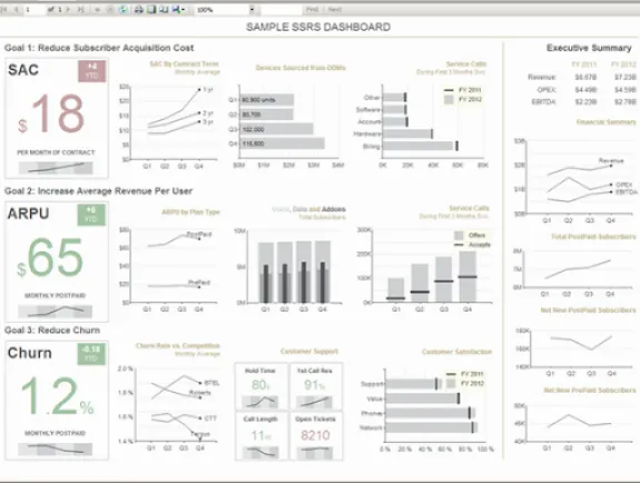
The other day, I was browsing for some sample SSRS dashboards and one of the top images that came up made me cringe. You might wonder what could be so bad in a dashboard as to make me cringe. Well, apart from the factor that the dashboard was openly flouting all the best practices for visualizations and that it would have misled countless people in virtue of being one of the top five images for the search term – ‘SSRS Dashboard’, it was made by ME. To be precise, this dashboard was made by me around 3.5 years back, a time when I believed more in ‘eye-candy’ rather than effective visualizations. That was when I felt that I owed a proper SSRS dashboard to the community.

First of all, let me start by saying that this dashboard was inspired (a polite way of saying – a complete rip-off ) from this Dundas Dashboard example. Personally, I felt that this was a very good dashboard example and I decided to reproduce it in SSRS. The result is given below:-

SSRS Sample dashboard

Let me tell you some of the things that I like in this dashboard:-

1) The colours are carefully chosen. Note how the dashboard is not a kaleidoscopic combination of different colours like it’s predecessor. Light tones of grey are used to depict the axis as well as the gridlines, while the charts are more darker which gives them more attention.Also, in spite of having 4X times more information than the previous dashboard, the new one doesn’t look crowded (thanks to the right choice of colours)

2) The dashboard focuses on the three main KPIs but also has an executive summary on the right. I also like the way each line represents a story for that KPI.

3) I particularly like the KPI boxes on the left. Each box has a current value (which is highlighted by the size), difference from YTD (which is the small box on the top right), a sparkline on the bottom as well as conditional formatting to show whether the KPI is above or below the target. I think it gives a sexy eye-candy sort of feel to the dashboard without bending the visualization best practices. Also, I prefer the faded red and green colours to the normal traffic light red and green colours that we see in usual dashboards.

4) The labels are all formatted appropriately (for eg, 3M instead of 3,000,000). This ensures that we don’t waste a lot of space for labels. With that said, let me go ahead and show you some of the tips and tricks I employed for making this dashboard:-

I) Alternating Background for the sparkline

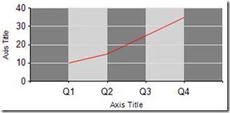
You can see the above sparkline (which is for the four quarters) has an alternating background for the four quarters. By default, you can have alternating colours in SSRS chart background if you set the background color of the chart area to a color (say light grey) and the InterlacedColor property of the X axis to another color (say dark grey). Now the problem is that the line charts will start at the meeting point of the two colours (like shown below) instead of at the centre.

Normal alternating background for sparklines

One of the ways you can get this done is by adding 4 striplines to the X-axis. For the first and third stripline, ensure that the BackgroundColor is the same (lets say light grey) and the second and fourth should have the same BackgroundColor (which is dark grey). All the striplines should have a Stripwidth of 1. The IntervalOffset property should be 0.5, 1.5, 2.5, 3.5 respectively for the four striplines.

Click on the Y axis and press the delete button to remove it. For the X axis, click on it and set the LineStyle property to None, Major TickMarks->LineStyle to None and HideLabels to True. This will give us the required result below. For use in the dashboard, remove the chart border also.

II) Pretty KPI boxes

The pretty KPI boxes are just a combination of textboxes and the sparkline we made above. This is how it actually looks in design mode

Right now, I have hardcoded most of the stuff. But you can change it as required. For eg, to get the conditional formatting, you can write a simple expression in the Color property of the textbox. The only other thing is to have different font sizes / font styles for the $ and numeric value. To demonstrate that, I pull in a textbox and type $ in it. After that, I drag and drop a field from my dataset (SAC) to the textbox.

ssrs textbox

Now I can individually select $ and give it a different font style / font size and also do the same for SAC (whose expression I modified to =Sum(Fields!SAC.Value, “G1_B1”) from =Fields!SAC.Value)

ssrs textbox - selected text properties

III) Formatting the labels

To format your labels in thousandss, you can use the format – 0,’K’

Similarly, if you want to format in millions, you can use - 0,,’M’. Note that you are just increasing a comma.

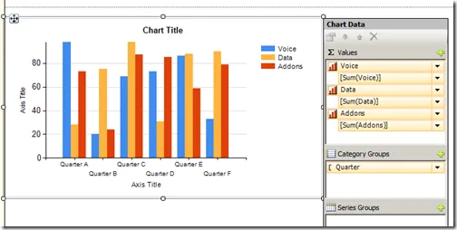
IV) Correlated column charts

For this, add a normal column chart with 3 measures.

column chart

Now change the PointWidth property of the second measure to 0.6 and third measure to 0.3.

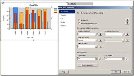
Now right click on the Chart Area, and click on Properties. Check the ‘Enable 3D option and set the rotation, inclination and wall thickness to 0.

3D option

After that, set the BackgroundColor property of the chart area to No Color. Now you should have the required correlated column chart.

Well, there are a few more tips in the dashboard that I made (even though I have hardcoded a LOT of stuff, since this was just a demo) and if you want, you can download the rdl file of this report from here. Hopefully, I have redeemed myself by creating a better dashboard than the original one!

Posted by SQLJason, 44 comments
100% Visualization in SSRS

100% Visualization in SSRS

Recently, Bill Jelen aka Mr Excel came up with a podcast that showcased a visualization that he termed as the “100% Visualization”. I have never seen this visualization before and I am not sure whether Stephen Few would approve of it. But I found the concept interesting and decided to exercise my grey cells by creating this in SSRS. Read on for the solution.

1) Create a new report with a simple dataset having Category name and percentage value

SELECT ‘Bikes’ AS Category, 82 AS Pc
UNION ALL
SELECT ‘Accessories’ AS Category, 49 AS Pc
UNION ALL
SELECT ‘Textile’ AS Category, 24 AS Pc
UNION ALL
SELECT ‘Furniture’ AS Category, 99 AS Pc

2) Make a simple tablix with 10 columns and 10 rows. Then fill the cell values from 1 to 100 as shown below

It is good to make all the cells of the same size and squares (for eg, size = 0.6,0.6)

3) Now make the border color as white, border style as solid, border width as 4pt and FontSize as 2pt.

4) Add the custom code below

Public Shared Function ColorDWB(ByVal Value As Decimal, ByVal MaxPositive As Decimal, ByVal Neutral As Decimal, ByVal ColStr As String) As String Dim ColVar1 As Integer
Dim ColVar2 As Integer
Dim ColVar3 As Integer ‘Split the #RGB color to R, G, and B components
ColVar1=Convert.ToInt32(left(right(ColStr, 6),2),16)
ColVar2=Convert.ToInt32(left(right(ColStr, 4),2),16)
ColVar3=Convert.ToInt32(right(ColStr, 2),16) ‘Find Largest Range
Dim decPosRange As Decimal = Math.Abs(MaxPositive - Neutral) ‘Find appropriate color shade
Dim Shd As Decimal = 255

Dim iColor1 As Integer
Dim iColor2 As Integer
Dim iColor3 As Integer
Dim strColor As String ‘Reduce a shade for each of the R,G,B components
iColor1 = ColVar1 + CInt(Math.Round((MaxPositive-Value) * ((Shd - ColVar1) / decPosRange)))
iColor2 = ColVar2 + CInt(Math.Round((MaxPositive-Value) * ((Shd - ColVar2) / decPosRange)))
iColor3 = ColVar3 + CInt(Math.Round((MaxPositive-Value) * ((Shd - ColVar3) / decPosRange))) ‘Return the new color
strColor = “#” & iColor1.ToString(“X2”) & iColor2.ToString(“X2”) & iColor3.ToString(“X2”) Return strColor
End Function
Private colorPalette As String() = { “#C85200”, “#FF800E”, “#5F9ED1”, “#2CA02C”, “#A59D93”, “#B8341B”, “#352F26”, “#F1E7D6”, “#E16C56”, “#CFBA9B”} Private count As Integer = 0
Private mapping As New System.Collections.Hashtable() Public Function GetColor(ByVal groupingValue As String) As String
If mapping.ContainsKey(groupingValue) Then
Return mapping(groupingValue)
End If
Dim c As String = colorPalette(count Mod colorPalette.Length)
count = count + 1
mapping.Add(groupingValue, c)
Return c
End Function

The GetColor() is used to select new colors for each category type and the ColorDWB() is used to get a lighter shade of the selected color (you might recognize the ColorDWB function from my post on Custom Code for Color Gradation in SSRS).

5) Add the expression below for the Color and BackgroundColor property for all the cells.

=iif(Me.Value <= Fields!Pc.Value, Code.GetColor(Fields!Category.Value), Code.ColorDWB(2, 10, 1, Code.GetColor(Fields!Category.Value)) )

6) Add a textbox on the top with the Category value, and a textbox below with the Pc field value and place all three objects inside a rectangle to keep them together. You can also format it by adding a background color of Green and a border of White, if needed.

7) Now add a matrix with Category field on column group. Then, add the rectangle with the three objects inside the value field.

Now you can delete the row and the column for the matrix so that it looks like shown below.

8) Preview it to see the result.

Isn’t that pretty? And if there are more charts than what can be fitted in the horizontal way, you might want to check this post on how to repeat it horizontally as well as vertically. As always, you can download the SQL 2012 rdl file from here.

Posted by SQLJason, 10 comments
Bandlines in SSRS

Bandlines in SSRS

Sometime in January, visualization expert Stephen Few expanded on Tufte’s idea of Sparklines and came up with this new visualization called Bandlines. Bandlines use horizontal bands of color in the background of the plot area to display information about the distribution of values and you can read a detailed description on bandlines in Stephen’s article. Companies like XLCubed have already started integrating this within their products and it was only a matter of time before yours truly tried to replicate the same within SSRS. Read on for the solution.

One of the most important steps to reproduce this in SSRS is to find the percentiles (25th and 75th) in your dataset query. You can do it the hard way by coming up with the logic and then computing it within your dataset. I chose not to reinvent the wheel and used Richard Mintz’s (yes, the same guy who came up with the code behind Squarified Heatmaps in SSRS) SSAS stored procedure for the same. He has written an excellent post on how to compute percentiles in both SQL and MDX, so you can use his code depending on whether your source is a relational database or a multidimensional cube. For this demo, my source would be the AdventureWorks multidimensional cube. Follow the steps below to reproduce bandlines:-

1) Download the dll from here and add it to your SSAS instance as per the instructions at the end of Richard’s post. I have named the assembly as SPPercentile.

2) Make a dataset query which will show the Internet Sales amount for a product category and month with the year as a parameter (optional, dataset query for year parameter is not shown here). Also make 2 calculated measures which will show the maximum and minimum values for internet sales by category across the months.

WITH MEMBER measures.[maxP] AS
Max (
StrToSet ( @DateCalendarYear ) * [Product].[Category].CurrentMember * [Date].[Month Name].[All] * [Date].[Calendar].[Month].AllMembers,
[Measures].[Internet Sales Amount]
)
MEMBER measures.[minP] AS
Min (
StrToSet ( @DateCalendarYear ) * [Product].[Category].CurrentMember * [Date].[Month Name].[All] * [Date].[Calendar].[Month].AllMembers,
[Measures].[Internet Sales Amount]
)
SELECT NON EMPTY
{ [Measures].[Internet Sales Amount], measures.[maxP], measures.[minP] } ON COLUMNS,
{
NonEmpty ( [Date].[Month Name].Children, [Measures].[Internet Sales Amount] ) * [Product].[Category].[Category].AllMembers
} ON ROWS
FROM [Adventure Works]
WHERE StrToSet (
@DateCalendarYear
)

Note that the maximum / minimum will be the same for a category across all months. This is required for doing the scaling of the bandlines, and will be explained in a later step.

3) Make a dataset query for getting the 75th and 25th percentiles.

WITH MEMBER measures.[25th percentile] AS
[SPPercentile].ValueAtPercentile ( NonEmpty (
( StrToSet ( @DateCalendarYear ) * [Date].[Calendar].[Month].AllMembers * [Product].[Category].Children,
[Measures].[Internet Sales Amount] )
),
[Measures].[Internet Sales Amount],
.25,
TRUE,
“INC” )
MEMBER measures.[75th percentile] AS
[SPPercentile].ValueAtPercentile ( NonEmpty (
( StrToSet ( @DateCalendarYear ) * [Date].[Calendar].[Month].AllMembers * [Product].[Category].Children,
[Measures].[Internet Sales Amount] )
),
[Measures].[Internet Sales Amount],
.75,
TRUE,
“INC” )
SELECT NON EMPTY
{ measures.[25th percentile], measures.[75th percentile] } ON COLUMNS
FROM [Adventure Works]

Note that we are using the [SPPercentile].ValueAtPercentile() stored procedure and you can find the syntax in Richard’s post. Now we should be having the following three datasets.

4) Now that we have found out the percentiles, store their values in two hidden report parameters respectively – PC25 and PC75. Make sure that that the available values and default values are obtained from the corresponding field in DST_Percentile dataset as shown below.

5) Now drag and drop a matrix into the layout. Use the Categories on the rows and drag and drop a line chart to the values as shown below. In the chart, use Internet Sales Amount as the Values, Month Name as the category group and Category as the Series Group.

6) Make the max and min of the vertical axis as the maxP and minP fields. This will help in scaling the sparkline (yes, by now we have got the basic structure of a sparkline).

Also, remove the vertical axis, horizontal axis, legend and all other titles.

7) Add a value to the chart with the expression below.

=iif(Fields!maxP.Value <= Parameters!PC75.Value, Nothing, Fields!maxP.Value)

Make the chart type as Area Chart and color as #f5f5f5

This will act as the band for the values between 75 and 100 percentile, so ensure it is at the very top as shown in the picture above. If the max value for the category is lesser than the PC75, we don’t want to show this band.

8) Add another value to the chart with the expression below

=iif(Fields!maxP.Value >=Parameters!PC75.Value, Parameters!PC75.Value, Fields!maxP.Value)

Make the chart type as Area Chart and color as #d7d7d7

This will act as the band between 25 and 75 percentile and should be appearing on top of the 75-100 band, so ensure that it appears just under the previous value as shown in the picture above.

9) Add the last band by adding the expression below

=iif(Fields!maxP.Value <= Parameters!PC25.Value, Fields!maxP.Value, iif(Fields!minP.Value>=Parameters!PC25.Value, Nothing, Parameters!PC25.Value))

Make the chart type as Area Chart and color as #adadad

Again ensure that this value appears just under the previous one, as shown in the picture above.

10) Now, we can preview it and see the results.

From the markers, you can also note that there are 24 values. Out of that, there are 6 values in the 75-100 band, 12 values in the 25-75 band and 6 in the 0-25 band. So the percentiles are indeed working! And very quickly, you can make out that Bikes have more of their values in the 75-100 percentile, an extra bit of information that you wouldn’t have got with sparklines. That is the power of Bandlines.

11) Now with a bit of formatting, this is the final end result and you can download the completed report rdl (SSRS 2012) from here.

Posted by SQLJason, 0 comments
Custom Code for Color Gradation in SSRS

Custom Code for Color Gradation in SSRS

Throughout my career as a Business Intelligence Consultant, I have met and interacted with a lot of DBAs. One thing (among many others) I particularly admire about them is that they have their own list of SQL scripts that they carry with them from job to job (and my observation is that the list usually grows with experience). This way, they don’t have to remember all of them, but when the need arises, they have the scripts at their fingertips. The only thing I have close to that is my list of custom codes for doing some specific operations in SSRS. One of my most frequently used scripts originates from this series of posts on how to conditionally color in SSRS. Based on my needs, I had tweaked the code such that it will display the color gradation to white for any input color. Thought that this might come in handy for some of you guys.

Code

Public Shared Function ColorDWB(ByVal Value As Decimal, ByVal MaxPositive As Decimal, ByVal Neutral As Decimal, ByVal ColStr As String) As String
Dim ColVar1 As Integer
Dim ColVar2 As Integer
Dim ColVar3 As Integer ‘Split the #RGB color to R, G, and B components
ColVar1=Convert.ToInt32(left(right(ColStr, 6),2),16)
ColVar2=Convert.ToInt32(left(right(ColStr, 4),2),16)
ColVar3=Convert.ToInt32(right(ColStr, 2),16) ‘Find Largest Range
Dim decPosRange As Decimal = Math.Abs(MaxPositive - Neutral) ‘Find appropriate color shade
Dim Shd As Decimal = 255

Dim iColor1 As Integer
Dim iColor2 As Integer
Dim iColor3 As Integer
Dim strColor As String ‘Reduce a shade for each of the R,G,B components
iColor1 = ColVar1 + CInt(Math.Round((MaxPositive-Value) * ((Shd - ColVar1) / decPosRange)))
iColor2 = ColVar2 + CInt(Math.Round((MaxPositive-Value) * ((Shd - ColVar2) / decPosRange)))
iColor3 = ColVar3 + CInt(Math.Round((MaxPositive-Value) * ((Shd - ColVar3) / decPosRange))) ‘Return the new color
strColor = “#” & iColor1.ToString(“X2”) & iColor2.ToString(“X2”) & iColor3.ToString(“X2”) Return strColor
End Function

How To Use

1) Lets say we have a simple report which shows the sales by vehicle type and month

2) You can either compile this code and use it in your report or just paste it in the code tab of the Report Properties. If we just need to get different shades of a color (say #2322EE), we can just use the expression below as the BackgroundColor property of the cell.

=Code.ColorDWB(sum(Fields!Sales.Value), Max(Fields!Sales.Value, “DataSet1”), Min(Fields!Sales.Value, “DataSet1”), “#2322EE”)

Color gradation across entire table

3) If you need the color gradation to be based on each row, then make sure that the max and min values are passed for the row (in this case, the Vehicle group) rather than the whole dataset.

=Code.ColorDWB(sum(Fields!Sales.Value), Max(Fields!Sales.Value, “Vehicle”), Min(Fields!Sales.Value, “Vehicle”), “#2322EE”)

4) If you need different colors for your vehicle, you can make use of the GetColor() custom code and then pass that in your expression:-

=Code.ColorDWB(sum(Fields!Sales.Value), Max(Fields!Sales.Value, “Vehicle”), Min(Fields!Sales.Value, “Vehicle”), Code.GetColor(Fields!Vehicle.Value))

Just make sure that the colors in the palette are using the hex values and not just strings like “Red”.

5) You can also use this code to go across two colors. For eg, what if we want to go from Blue to White to Orange such that the mean is white, more is blue and less is orange? We can write an expression as shown below

=iif(sum(Fields!Sales.Value) >= (Max(Fields!Sales.Value, “DataSet1”) + Min(Fields!Sales.Value, “DataSet1”))/2,
Code.ColorDWB(sum(Fields!Sales.Value), Max(Fields!Sales.Value, “DataSet1”), (Max(Fields!Sales.Value, “DataSet1”) + Min(Fields!Sales.Value, “DataSet1”))/2, “#6495ED”),
Code.ColorDWB(-sum(Fields!Sales.Value), -Min(Fields!Sales.Value, “DataSet1”), -(Max(Fields!Sales.Value, “DataSet1”) + Min(Fields!Sales.Value, “DataSet1”))/2, “#FFC125”))

Note that we are writing a conditional expression to see if the current field is more than the mean (max+min / 2). If yes, then we use the familiar expression with the Blue color (so more the value, darker the blue). If no, we need to do add a negative for all the fields so that the coloring happens in the reverse order (lesser the number, darker the Orange).

Blue to Orange color gradation across entire table

You can keep on tweaking this code and use it for a wide variety of visualizations. I am no VB.NET developer, so it is possible that there is a much better way to do the same. If you do know of any better technique, do post in the comments so that others can benefit from it.

Posted by SQLJason, 30 comments